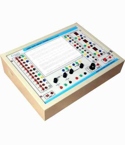
DIGITAL IC TRAINER
Price 12600 INR/ Piece
DIGITAL IC TRAINER Specification
- Equipment Type
- Laboratory Instrument
- Equipment Materials
- Stainless Steel
- Power
- 150 - 220 W Watt (w)
- Voltage
- 220 volt A.C Volt (v)
- Material
- SS
- Application
- Laboratory
DIGITAL IC TRAINER Trade Information
- Minimum Order Quantity
- 1 Piece
- Main Domestic Market
- All India
About DIGITAL IC TRAINER
"CROWN made DIGITAL IC TRAINER has been designed to perform the following experiments :
1 Study and verify truth tubes of Logic Gates (AND,OR, NOT NAND, NOR, EX-OR GATES USING TTL& CMOS ICs)
2 Verification of Boolean Identities & Demogran's Theorems.
3 Study and verify truth table of Digital Adder and Subtractor ( Half Adder - Subtractor , Full Adder - Subtractor & 4 Bit Adder & Subtractor Using IC 7483 & 7486).
4 Study of RS, T, D & J-K Flip-Flops and verification of their truth tables.
5 Study of Synchronous, Asynchronous, Decade & Johnson Ring Counters.
6 Study of Left , Right & Programable Shift Registers and Verification of their truth tables.
7 Study of BCD to 7 SEGMENT Decoder.
8 Study of BCD to DECIMAL Decoder.
9 Study of DECIMAL to BCD Encoder.
10 Study of 8 -1 Line Multiplexer.
11 Study of 1-8 Line Demultiplexer.
SPECIFICATION
INPUT : 230V AC -+ 10%.
DC OUTPUT : A) -+ 5V/500mA
B) 0 -+ 25V/500mA
1. Bread board having 1680 tie points is mounted on front panel.
2. 12 logic input with LED indicator using SPDT switch.
3. 12 nos. Logic output with LED indicator.
4. 1Hz mono shot clock pulse with pulser switch.
5. TTL clock pulser having output frequency!s of 10Hz, 100Hz,1KHz & 10KHz selectable By switch.
6. Three (2 Nos. Common Anode LT542 & 1 No. Common Cathode LT543)Seven segment display connected with sockets for each segment
7. Two Potentiometer of 1Kohm & 1 Mohm.
Superior Build and Reliable Performance
Designed with stainless steel components, the Digital IC Trainer offers durability and resistance to wear in frequently used laboratory settings. Its high-quality materials make it suitable for long-term use, even under intensive educational or research activities.
Versatile Laboratory Application
This instrument is a valuable asset for laboratories, serving as a practical training platform for students and engineers. It enables interactive experiments, circuit analysis, and simulations, enhancing both teaching and learning experiences in digital electronics.
FAQs of DIGITAL IC TRAINER:
Q: How is the Digital IC Trainer used in laboratory environments?
A: The Digital IC Trainer is utilized in laboratories to facilitate hands-on learning and experimentation with digital integrated circuits. Users can construct, analyze, and test different circuit configurations in a controlled setting.Q: What materials are used in the construction of the Digital IC Trainer?
A: This trainer is manufactured primarily using high-grade stainless steel, providing strength, longevity, and resistance to corrosion, which is essential for regular use in laboratory conditions.Q: When is the ideal time to implement the Digital IC Trainer in educational settings?
A: The Digital IC Trainer is best employed during practical sessions, demonstrations, or workshops focusing on digital circuits, allowing students or trainees to gain real-world insights and experience at any stage of their learning.Q: Where can I purchase or source the Digital IC Trainer?
A: The Digital IC Trainer is available for purchase through exporters, manufacturers, suppliers, and traders located in India. It may also be obtained through authorized laboratory equipment distributors.Q: What is the process involved in operating the Digital IC Trainer?
A: To operate the Digital IC Trainer, connect it to a standard 220V A.C power supply, and use the interface to configure and test various IC-based experiments as per the laboratory curriculum or individual requirements.Q: What benefits does the Digital IC Trainer offer to users?
A: This equipment provides robust learning opportunities, enabling practical understanding of digital electronics. It is reliable, safe, and boosts both teaching efficacy and student engagement through hands-on training.

Price:
- 50
- 100
- 200
- 250
- 500
- 1000+
More Products in ELECTRONIC TRAINING BOARD FOR VARIOUS LABS Category
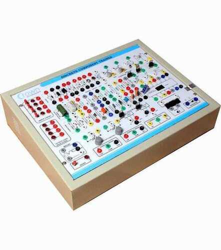
DISCRETE COMPONENT TRAINER
Price 10600 INR / Piece
Minimum Order Quantity : 01 Piece
Equipment Materials : Stainless Steel
Power : 150 220 W Watt (w)
Equipment Type : Laboratory Instrument
Material : SS
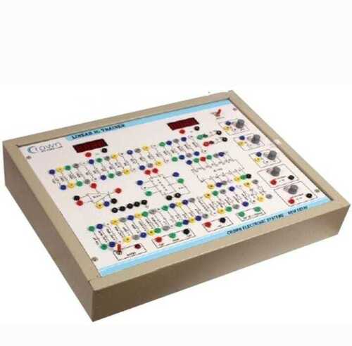
LINEAR IC TRAINER
Price 13300 INR / Piece
Minimum Order Quantity : 01 Piece
Equipment Materials : Stainless Steel
Power : 150 220 W Watt (w)
Equipment Type : Laboratory Instrument
Material : SS
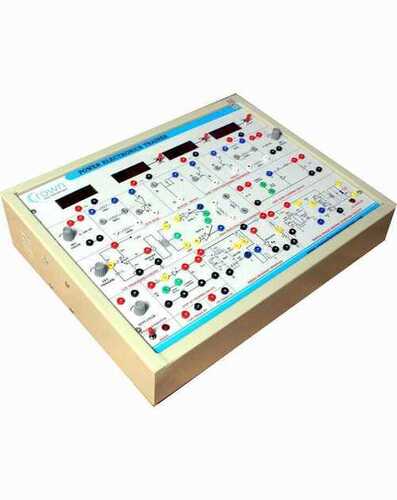
POWER ELECTRONICS TRAINER
Price 22000 INR / Piece
Minimum Order Quantity : 1 Piece
Equipment Materials : Stainless Steel
Power : 150 220 W Volt (v)
Equipment Type : Laboratory Instrument
Material : SS

 Send Inquiry


 Send Inquiry
 Send SMS
